So about those tiny motors…
There are fundamentally 2 types of DC motor – brushed and brushless. In a brushed motor, the external housing, or “can” is static, and has a couple of magnets glued to it. Floating in the middle of the can is a coil of wire with 2 ends (let’s call them A and B), which are wrapped around the shaft. The shaft is supported at each end of the can. So the outside of the motor is sealed, and strong, and solid, but the inside has some issues. The web is full of basic DC motor tutorials (even wikipedia!), but the short story is that when you pass current through the coiled wire, it induces a magnetic current that repels the magnets, and starts to spin. But as it spins, a couple of things happen. Firstly, obviously, if the wires coming from outside the motor are just coiled around the shaft, they will start to tangle. Secondly, as the coil moves, sooner or later the polarity of the wire and the magnets will line up so that they attract, rather than repel. At which point you can stop worrying about tangled wire, because the motor will lose torque. It probably won’t stop, thanks to momentum, but it’s certainly massively inefficient.
So small DC motors like that have “brushes (or “commutators”, if you’re being fancy) on the shaft and the body. It’s an area of the shaft that literally brushes against a patch on the body, and current is transferred through that contact patch. So by having a patch for each end of the wire (A and B), and an insulated area between them, you are constantly switching the polarity of the winding on the shaft, and freeing the shaft to move. That’s basic DC brushed motor theory – current induces a magnetic field in the wires, magnets repel the wire, shaft turns, brushes switch so that the shaft polarity reverses when it gets to the next magnet, that magnet repels it so it keeps travelling.
Brushed motors have a couple of solid advantages:
1) The shaft can be supported at both ends of the motor can. That makes it pretty robust, since usually the can will be attached to some kind of chassis at the shaft end. Minimum of distance between motor support and shaft support means minimum of leverage and bending when you get a load on the shaft – like when you’re trying to put a robot on a wheel attached directly to the shaft.
2) They’re dead easy to control. You run DC of whatever voltage to the inputs, and that’s it – all the switching and commutation is internal and hard wired.
The downside, of course, is that brushes wear out, and spark, and generally get dirty, and that “simple” control means fairly brute control – you can’t do much beyond varying the voltage (either by reducing it or by “pulsing” it).
So what happens if you hold the wire static, and let the can rotate? Well, two things. Firstly, you have to re-design the can housing so that the wires come in at a fixed base, and the can is supported from that base.
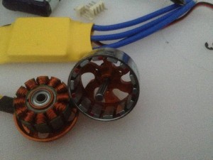
Here, it’s probably time for a picture:
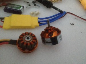
On the left is the wire coil, obviously. That’s called a “stator”, because it doesn’t move. Since the wires don’t move, you don’t need brushes, you can just run power straight to the coils. Hence, “brushless”. On the right is the rotor – the magnets rotate around the stator and turn the shaft. But here’s the thing. They only “rotate” if the wires repel them, and you have the same basic issue here – if you just run current to the wires, then the magnets and coil will initially repel, but then find equilibrium. So you need to actually switch the current between coils. Now, in a brushed motor, the point at which the wires and magnets repel and attract is a physical attribute, and by placing the brushes and patches appropriately, you physically control when the current switches so that it matches when it needs to switch. But on a brushless motor, there’s no physical switch. So the first “downside” to brushless motors is that control is hard. That yellow package behind the motor is an ESC – Electronic Speed Controller, and its sole purpose is to provide the brains to switch current between coils[0]. That’s a fairly stupid version, and it’s still as large as the motor (it is a tiny motor, I suppose).
The other problem is that although the shaft is still mounted on bearings in the stator, by necessity one end of the shaft has to poke through the rotor outside that bearing. That increases the length of unsupported shaft, making it more vulnerable to bending from the force of, say, a wheel.
You can see there where the shaft enters the rotor there’s a good few mm of housing for the shaft to pass through before it gets to the bearing. That’s quite a lot more leverage for a bending force. Not to mention that because the rotor is spinning, obviously, the stator is what gets bolted to the chassis. So the bolts are at the other end of the stator, which is a whole other can of bending force.
There is, however, an obvious solution. That shaft passes right through the stator, and is supported by a bearing at the other end. The only problem, of course, is that it passes through the stator just far enough to have a retaining clip on it to hold it in place. Nowhere near enough length to attach anything. It is, of course, possible to buy brushless motors with the shaft protruding at the stator end. I didn’t do that. I’m sure there’s a good reason for that, but I can’t imagine what it might be…
So I now have a few options.
1) I can dig around in my motor box for 3 matched brushed motors. That has a few advantages, not least of which is ditching the ESCs (I’m not actually running this off a remote control in the traditional way, I’ll be using a microcontroller to actually generate motor signal), but then we’re back to losing fine control, which may matter. And it’s not a great exercise in learning to control brushless motors 🙂
2) I can buy reverse shaft brushless motors. That’s another $50, but there are some very sexy black ones on eBay…. Still, it’s money I shouldn’t spend. Because although I’d then have 4 spare brushless motors ideal for quadcopter use (that’s why the shaft arrangement I have is common in the RC world – quadcopters put almost no side load on the shaft, and having the can rotate is fine), I’d then need four more ESCs and batteries….
3) I can reverse the shaft. Shafts like this are “press fit” in engineering terms. What you might think of as a “tight fit” for a shaft in a hole – if you can push the shaft in easily but not wiggle it much – is in fact terribly sloppy by engineering standards. If you have to work to push it in, then you’re approaching “interference fit”. For a proper fit, you need a mechanical press. So these shafts have been pressed into the housing, and would have to be pressed out, and back in again. I could probably manage that at home, but it’s a bit of a pain.
4) I can suck it and see. The shaft isn’t *that* far outside the bearing, and Tiwi is tiny, and besides, I have a spare…
So now I just have to work out how to attach an 8mm hollow axle to a 3.2 mm motor shaft, and I’m golden….
[0] Remote control brushed motors need ESCs as well, because remote controls basically send servo pulses, and the ESC then has to convert servo pulses to straight brushed current. Whole other post.


